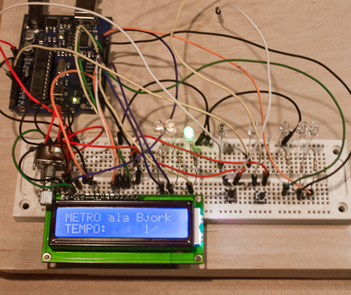
Creating a midi metronome was one of the first projects I tried to tackle with the Arduino. Pictured above is a simple circuit running a sketch to light LEDs alingned a row, sequenced to visually emulate the Q-Logic Midi Metro used by Bjork and several other artists. The actual commercial product is expensive, hard to find and (I believe) over 15 year old technology. It seemed like a good candidate for emulation.
The sketch running above was pretty simple. The two buttons increase or decrease tempo by changing a delay value between each step of a looping light sequence. “Tempo” arbitrary, and the actual time it took to complete a loop depended on whether (or how much) I wrote to the LCD. Because of this, I wasn’t sure I could come up with code that would provide a stable, musical tempo. Instead of trying to make the device an accurate timepiece, I decided the device should read midi beat clock, similar to how the Q-Logic Midi Metro is designed to work. This seemed simple but posed some interesting problems (see below.) Also, the circuit pictured is using most of the available Arduino pins: 6 i/o pins for the LCD, 8 pins for the LEDs, and 2 for the buttons. That’s just about maxing out the Arduino’s Input/Output pins, and it still doesn’t include Midi.
If Arduino represents one thing for me, it is a huge learning experience. Midi control of whatever I wish seems like a relevant goal, and could inform many projects I’d like to attempt. As I was learning to interpret serial midi data, I sidetracked and experimented with a few other ideas. One of these sidetracks was having the Arduino learn and re-transmit Infrared (IR) remote control codes using libraries shared on the Arduino website. Once I had the board reading midi ‘notes’ I could control an IR device by pressing a key on a midi keyboard. (I experimented using an cheap RGB LED strip that has an equally inexpensive IR remote.) That was cool, and potentially useful, but was still a far step from reading and usefully interpreting midi beat clock.
My strategy for the metronome is to read incoming midi clock signals, which are transmitted 24 times per quarter note. Each clock signal would have a corresponding ‘frame,’ or map of each LED’s on/off state stored in an array. Seems simple enough. However, how does the device know what clock signal represents the 1st beat of a measure? Moreover, how does it know which signal is the actual beat? What if the sequencer sending the clock signals starts or stops between quarter notes? These problems can likely be solved by reading and applying start/stop signals, but my schedule and sudden need to find a new house kept me from getting much further into the problem.
The other issue I ran into was my desire to control a bunch of LEDs and a display. At the time I started to work out this problem with a MAX7219 7-segment driver IC. This would allow me to drive 4 numeric digits and 20+ additional LEDs. Things have changed though, and when I revisit this project in the future I’ll likely use an I2C bus 7-segment display, and LED Pixels for the metronome LEDs…
The project you’ve created is just what I wanted. IMHO it is the only way really good to keep BPM.
I’m no expert in programming Arduino and in connecting the various components, but if you send me the code you’ve written and a wiring diagram maybe I could replicate the project.
I sincerely hope that you can help me.
Thank you.
Hi there, Pier. Sorry for the much delayed response. I last worked on this project about 5 years ago and never finished. I may look into it again soon 🙂
Hi,
I have been looking for such an hardware for hours. I’m about to buy a Q-Logic metro second hand but I find crazy that nothing has replaced this usefull device in the huge choice we nowadays got on the digital music’s market…
I’m french and found funny the display on the picture “Metro à la Björk”, sounds typiccally french!!
I don’t think I’d be able to build yours but if you have well documented its building why not (I love handworking but I don’t have a lot of experience with electronic)… do you share your projects’s drawings?
Congrats for this intersting job, all the best.
Sam
Hey Sam, sorry for the much delayed response. Q-Logic owns a patent on the way the light display works for the Midi Metro, which is probably why no one has designed another commercial unit.
I never did get around to wrapping up this project, though it did start me down a path to learning more about physical computing and writing code. I hope to look into this again maybe later this year, as things have changed quite a bit as far as the hardware available, as well as my understanding of code. 🙂