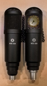
This is my second post on modifying Oktava MK-319 microphones. See part 1 here.
I’ve always been fascinated with Russian engineering and technology. This was my first opportunity to hack into some of it. I’ve used a few relatively inexpensive Russian Oktava microphones on several recordings. While not quite Neumanns, they sound surprisingly good on a lot of sources. For a few years they were the featured discount condenser mic at Guitar center, so they are easy to find on eBay and elsewhere. It turns out the capsules and transformers in these are pretty nice, but the supporting components and circuitry are often compromised. Also, the design of the microphone’s body causes some strange resonances. As I mentioned in a previous post, there are at least a few techs who have built businesses out of modifying, upgrading and drastically improving the sound of these microphones. After doing a bit of research I decided to try making some of these modifications myself. For about $50 I was able purchase all of the parts and materials to modify two Oktava MK-319 mics, with some components to spare. A few of the parts were hard to source, and it took about a month for everything to be shipped. These modifications are based directly on this article by Scott Dorsey, Micheal Joly’s Oktavamod.com, and also on forum discussions including Bill Stitler and Jim Jacobsen. I take no credit for the ideas, but offer my insight as a kind of newbie at DIY audio and recording hacks.
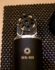
The first step is to remove the screws for the headbasket. There is only one screw at the base of the microphone that holds the XLR jack, the circuit board and the capsule in place.
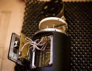
There are four smaller screws holding the rear panel in place. According to the photos in Dorsey’s article, it looks like my microphones are the 4th Revision. In addition to the -10db pad and low-cut switches, there is a small circuit board attached to the panel. This will be entirely removed from the circuit; bypassing all of the extra wire, components, and connections between the capsule and FET. The functionality of the switches will be lost. However, there will be much less crap for the capsule’s tiny signal to pass through. Later on, there was some confusion matching up the components on my circuit board to Dorsey’s schematic. I had to remember there were 2 capacitors on the rear panel’s circuit board, which I had set aside: C1 and C4 in the schematic.
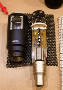
Once the wires to the back panel are cut, some kind of modification is going to happen! This picture shows the unmodified MK-319 circuit board. The FET, 4 of the resistors and 7 of the capacitors will be replaced, along with the plastic resonator disk attached to the capsule. The first components are relatively easy to identify.
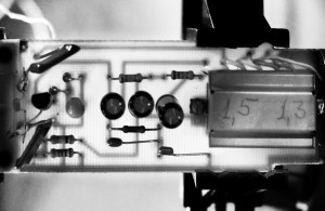
Oktava issued several revisions to the stock MK-319 circuit board. To be sure I didn’t mix things up, I took this backlit photo of the PCB, so I could better compare my board to the schematic. Several forums have mentioned the how fragile the board is. It’s nearly transparent! However, I didn’t find it too difficult to work with.
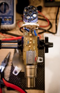
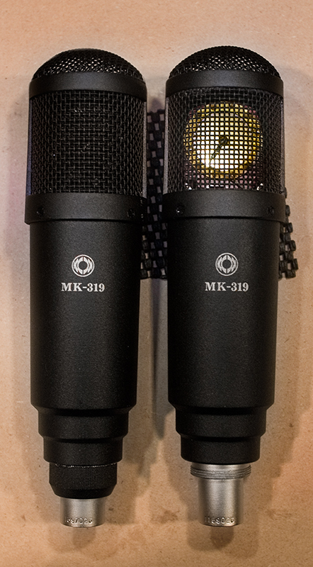
In addition to the electronic component upgrades, there are several common mechanical improvements I wanted to try. Many who have modified Oktava 319’s remove the inner layer of the headbasket grill. This is supposed to provide a more “open” sound, with less reflections bouncing around the capsule.
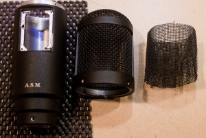
Removing the inner mesh was much easier than I anticipated. The hardest part was initially separating it from the outer headbasket enough to grip it with needle-nose pliers.
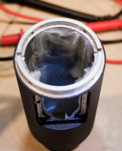
The original, unmodified MK-319 has noticeable resonance if you tap it. The body “rings” almost like feedback. Dorsey’s article recommends damping this resonance with silicon RTV caulking. This took about 48 hours to dry completely. There is a limited amount of space for the circuit board. I added too much and ended up cutting some of the silicon away.
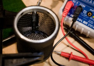
With the stock 319, the headbasket presents the biggest resonance problem. Even without the inner mesh, the grill is very rigid and distinctly rings when struck. The best solution is to fashion a completely new basket with a brass, or more a flexible metal mesh. Several discussions have suggested the grill must be grounded to prevent electrical noise. Short of removing (and destroying) the entire original grill, I decided to carefully apply silicon RTV to the headbasket base and supports, to see if it helps. Fashioning a completely new mesh grill seemed a little overboard, and I didn’t really have the appropriate materials.
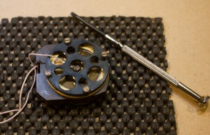
The last modifications I made were to the capsule and capsule mount. The stock 319 has plastic resonator disks attached to both sides of the capsule. These reflect some high frequencies back to the diaphragm and provide a “presence” boost. Most people remove these, and so did I. The danger here is slipping with the jewelers screwdriver and punching a hole in one of the really great stock parts of the microphone. So I had a couple cups of coffee and gave it a shot.
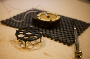
While I was adding silicon to the body and headbasket, I also made a sort of ramp around the base of the capsule mount. Then I placed a bit of felt between the mount and the capsule. My intentions were to dampen any vibration and reduce reflections off of the plastic disk, which separates the circuit compartment and headbasket.
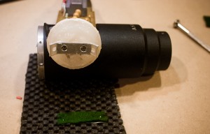
And that’s it. I reassembled the mic and, thankfully, everything worked the first time I plugged it in. I don’t have any audio files to share at this point, but so far it sounds noticeably improved. A shock mount will be absolutely required. Simply bumping the mic stand causes low frequency rumbling (from the mic stand vibrating) that was imperceptible before the modifications.
I have one more mic to mod, and I’ll probably try to make a new headbasket for it. There is still a lot of resonance, which is even more noticeable now that the microphone is otherwise superior. The small amount of silicon RTV I applied to the original headbasket helps a little bit, but it still rings very noticeably when bumped or tapped. I imagine this must have an effect on the sound. Still, the modified mic is a drastic improvement that was well worth the time and effort!
Awesome.. how do I bypass the switches? Any pics of rewiring the switch wires? Do I need to jumper them?
Cheers
Thanks
Tim
Hi Tim,
As I recall, I just snipped the wires and no jumpers were required. Check out the schematic from Scott Dorsey’s article I linked above:
Article:
http://www.recordingmag.com/resources/resourceDetail/316.html
Schematic:
http://www.recordingmag.com/downloads/diy_schematic2.jpg
It looks like the circuits through C1, C4 & R5 are open when the switches are not engaged (you could probably confirm that by doing a continuity test with the switches disengaged….) Since there was apparently an open circuit anyway, just chopped it off.
Thanks for reading!
Marshal